Saturday, 18 October 2014

The Traverser

Finally I have something new to add.

This week I built the traverser. For anyone wanting to make a similar one, the frame is built from ply on the ends and top, and 65x12mm dressed-all-round pine. The frame is 1450mm x 450mm, with the left-hand entry being 250mm long and the right-hand one 200mm.

The table itself is 40x18mm DAR pine and ply on top, and measures 350mm x 990mm. I bought 300mm drawer runners from this company online and received them by courier within a week for about $27 all up.

Here it is with the table fitted, showing the construction

And when complete.


 The handles were from Bunnings and just add a nice finish.


I bought fully-extending drawer slides to maximise the traverse of the table and get as many roads as possible onto it. Part of this involved building the table one road-width wider than the drawer slides. As you can see in the picture above, the outer slide is affixed to the frame and the table is affixed 50mm from the end of the inner slide.

In the picture below, the table is fully extended out. When installed, the entry road will align parallel with the inner right-hand side of the table.


Once the drawer slides are fully closed, you can see that the entry road now aligns with the inner left-hand side of the table.


Pretty straight forward idea, derived from a lesson learned on my previous layout where the drawer slides I bought from Ikea only allowed for a 200mm traverse, despite being 300mm long.

Next job is to build the legs for this, and the right-hand return loop. Both should be fairly quick jobs, so it won't be long before there's some more permanent track down and I can move from carpentry to modelling.

Cheers,
Ben

Monday, 6 October 2014

Liverpool 2014

Progress photos were promised, and I'll come to that in a bit. For now, I just wanted to give a quick review of the 2014 AMRA Exhibition at Liverpool.

I went with the super-keen Saturday crowd, queuing up at 8.30 on Saturday, and making a beeline for Austrains when the door opened. With both them and Auscision promising sales it was a bit of a gamble, but after seeing a weathering demonstration by Aaron Denning at the Thronleigh exhibition I wanted to get another pack of WHX hoppers, which I did - $110 for four! Pretty happy with that, but weathering will come after I get an airbrush in a few months once the track is down. 

The surprise Auscision locomotive was revealed as being the 421, and the samples certainly look the goods. Although they fit my era, I've always seen them as out of my loose conformance to a western/north-western division theme. In the display case they shall stay. 


In addition to the WHX's my haul from the show was light at a pack of SDS's SRC containers, and a German-language magazine I annually hang out for from the Orient Express stand to refresh my language skills. The rest of the haul went to the family to be gifted at a later date during Christmas or birthdays, which will see the workbench will graced with a Silvermaz TRC kit to detail with an IDR underframe, and an IDR Castings OSF, 

It was good to see a running sample of the Trainorama 48 on Geoff Small's 'Ashburn' too. As you would imagine with anything you paid for eight years ago, I spent a lot of time studying it as it towed a short mail train consist around. If you couldn't get to the show to see it, it looks like it won't disappoint. I've ordered an Auscision one recently too (with 165 in the class, you can never have too many!). Apparently the Auscision 46 was getting around on Ashburn later on the Saturday too.

Turning briefly to 1:1 scale, I left the exhibition after lunch for a wedding near Wollongong. I got changed at the Engadine Macca's, which is right next to the railway line. Going back to the car something loud and determined shot past in the cutting next door, heading south. As I was heading down that way anyway, I jumped in the car and headed to Stanwell Park station to see these 82's roll through. It was a nice end to the trains for the day.


Back to the layout.

A few other bloggers have extolled the virtues of the Connect-It range of aluminium lengths and plastic connectors from Bunnings, so I picked up some over a few nights last week and built the legs to support the modules on Friday afternoon. 


Aside from the light weight and strength, probably the biggest benefit is the speed with which you can knock together almost anything with these. I built the legs in less than an hour, probably closer to 40 minutes.


After that, my attention turned to carefully cutting the backdrop with a hobby knife and separating the module. For what is going to be a portable layout, the two modules had been bolted together since February. Separately them for the first time is kind of a big thing. Next, they were both moved upstairs with the help of my ever-patient partner.


Voila!


It feels encouraging to get to this point, so I got some track and rollingstock out to have another look with a little more done. The track boards appear to not be level on the left-module, despite being level when they were installed in the garage, so I'll need to have a play around with that before track can be laid.


I started building the traverser module this afternoon before my interest in spending more time in the garage waned. It's something I will get to, however next up is fitting the pelmet and painting it. I wanted to keep that part off until everything was upstairs to allow for any adjusting if required, but so far it's looking ok to do later this week.

Until then, happy modelling!

Cheers,
Ben


Monday, 29 September 2014

Passing the Liverpool distance signal

I've been to every one of the AMRA exhibitions at Liverpool since the early nineties, including the side show to Hurstville, so it's been a landmark in my calendar for as long as I can remember. Going to the show inspires me to consider different scenery, operating procedures or train composition and detailing in my own modelling, and overall I usually walk away with a few new ideas and a kit or two. Falling on the October long weekend, it also heralds the start of a season of the year more conducive to modelling; more time through annual leave and daylight savings, warmer weather, all punctuated by the requests for stocking-fillers by the family for Christmas. Another InFront Models sleeper wagon? Hmmm. I do need one of those. Thanks Santa!

With the exhibition now truly in sight for this year, I am predicting the urge to want to get track down pretty much as soon as I get home. I have an imperative to finishing painting and moving the layout upstairs.

This weekend just past saw the fascia, ends and underside of the lids undercoated in preparation for sky blue to be applied to the lids to be less distracting in photos, with black on the fascia to complete the shadow-box effect.


The return loop was also painted black and dried quite quickly on Sunday. It's now sitting upstairs in the train room. One down!


Tomorrow will see the lids and hopefully the fascias painted. You by now get the idea of where it's up to and where it's heading so I'll keep it mostly to photos until we get to something new. 

Like tracklaying.

Cheers,
Ben


Wednesday, 3 September 2014

One step forward...

Last week it rained in Sydney. Brilliant, I thought; indoor weather and plenty of time to do some more to the layout.

Until I arrived in the garage. 

With limited insulation and ventilation in there, the moisture from a few days' worth of rain had built up and warped all of the MDF components of the modules - namely those which I had only just completed!


So, after a quick trip to Mister Ply & Wood for some 4mm B grade external plywood, I'm now back to where I was three weeks ago. Lesson learned.


On the plus side, I had do a little landscaping to get the fascia fitted, so a little more has been completed and I've been prompted to think about the final scenery shape. The block of wood in the below photo is sitting where a retaining wall coming off the overbridge supports will go.   


Happy modelling!

Cheers
Ben


Wednesday, 13 August 2014

Quick update

Progress of late has seen the fascia nearly finished, the pelmet cut, and the 'lid' for the modules cut and fitted. All of the latter components have been made from 3mm MDF sheet, reinforced either with dressed-all-round pine or the steel frame. The lid is a plug design to allow for removal in case I can't get the grassmaster in there later on. More on that in a future post.

These are the last major construction components for the modules, so I took the opportunity last night to lay some of the track out and the Austrains' BSR and see how it's all coming together. Next up will be taking the jigsaw to the contours of the fascia, covering over the screw holes with filler and painting the exterior timbers black.


'Til next time!

Cheers,
Ben

Sunday, 20 July 2014

Installing the LED strip lighting

Like most beginners I suppose I’m a bit wary of committing money to anything before I have a good idea of how it all comes together. When I’ve scoured other people’s blogs and forum posts I’ve often been inspired but left wondering how they did it. In some cases a quick email brings back an answer, but for the times when you have fifteen minutes to kill on the train or waiting to board your delayed Virgin flight – again – having that info a google search away can make some of that armchair modelling time a little more useful. To that end, this post is heavy on detail and light on photos.  If you’re in a similar predicament, feel free to comment below and I’ll try to answer as best I can.

So, the lighting.

As mentioned in previous posts, I bought a roll of Warm White 5M SMD 3528 LED Flexible Strip Lights and Cool White 5M SMD 3528 600 LED Car Flexible Strip Light from China via eBay, as well as a 12V 6AMP power pack and a 2.1mm screw terminal connector.

This thread on layout lighting was a really good source of info and if you ever read this Linton, I appreciate your time posting it in the first place.

The LED strip is about 8.5mm wide, so I spent an entire day trying to find an appropriately sized dovetail bit - most of the ones I found were 10mm wide and over. In the end Part no H1012 from Carbitool (7.1mm dovetail router bit – catalogue available here) was backordered from the local tool shop.


I routed a test piece of timber (above) to get an idea of how to use the tool and found that after the first cut I needed to make a second to widen the gap by another millimetre or so. The timber used to for both the support for the LED strips and the lighting timbers was 12mm x 65mm pine from Bunnings. After the grooves were cut with the router, I attached the lighting timber to the supports using two 65mm butt hinges, also from Bunnings. The screws to hold the hinges in are longer than the timbers, so they protrude through. On the lighting timber this protrusion will be covered by the pelmet, but I need to figure out something for the top ones to prevent sticking it in my fingers in future.

The LED strips were then laid out and squeezed to make them rounder and easier to press into the grooves. The groove was a tad too tight to drag the strip through, but pressing it in gently with a small flat screwdriver worked a treat. I then cut the LED strip at each end across the copper joins as marked on the strips.


To finish the electrical connection between the strips, I bought these 2.1mm DC socket and plug with screw terminals from Jaycar. I soldered the wires to the LED strip and covered them with 5mm heat shrink tube (also from Jaycar) before attaching the other ends to the plug and socket.


Once all of this was test fit on the modules, and the electrical connectivity tested, the supports were screwed to the module. Despite the urge to press on and get the lighting in, it was easier to fiddle with the wiring still be able to pull the whole system out to adjust or re-solder anything

The end result is:


The backscene was wrapped with bubblewrap right at the beginning to protect it from any filings or inadvertent bumps that would ruin or dent a very expensive part of the process. In short, a sanity preserver. It will come off once I’ve finished the woodwork and painting. Running trains is getting that much closer!

Next to cut, fit and paint the pelmet.

Cheers,
Ben

Sunday, 29 June 2014

Backdrop done

Not long after the last post, my Fastracks turnout kit and the remaining backscene arrived in the post. So, over the past two weekends I’ve been attaching the custom sky backdrop I mentioned a few posts ago.

The process is best described in this video, but in a nutshell, here’s how I did it.

I had to sand a few divots and blemishes on the backboard, hence the white marks you can see in the belowe photo. After laying the first backdrop I noticed I hadn’t got all of them, so the second module had a more aggressive preparation with the sandpaper.


I started with the left-hand module, cutting slots for backdrop to fit around the baseboard using a hobby with fresh blade.


To start the whole process off, I clamped the backdrop to the backboard, checking the fit and ensuring everything as going to fit flush.


Then, I removed the clamps on the left and raised the first 30cm or so off the backboard, separating the backing from the adhesive vinyl. I then grabbed the scissors and cut the now-separated backing away. Using a clean paint roller, the free part of the adhesive vinyl is rolled onto the backboard, while the clamps on the rest of the backdrop hold it all in place.

This is where the time spent in preparation pays off. With the first part down, the clamps were removed from the rest of the backdrop, and the remaining backdrop is rolled up to where the secured part is. The backing is peeled away from the next part, and rolled out slowly and secured to the backboard with the roller.


One module done!


This process was then repeated from the other end until all of the sky backdrops were secured.


Next, I trimmed the Haskell ‘Barinore’ backdrops and sighted them on the backdrop... 


...before adding them too.


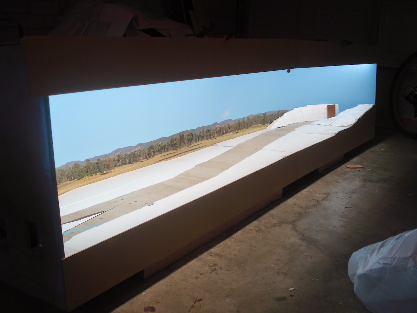
I’ve added the foam scenery back afterwards and I’m pretty happy with the result.


A few points about adhesive vinyl backdrops
Once adhesive vinyl meets adhesive vinyl it puts its roots down and makes home. While the vinyl would lift off the timber backboard easily and allow for realignment, I discovered when laying the landscape backdrop onto the sky backdrop that you only get one run at it. Pulling it up to realign it will bring the colour off the lower backdrop. The first landscape backdrop started to ‘walk’ down the bottom of the sky backdrop, only by about 2-5mm, but enough to cause concern on how to get it back on course again.

With such a thin piece of material, trying to ‘walk’ it back onto the right trajectory can cause air bubbles as the vinyl bends. Going slowly and being patient is the key here. We got it back into the right spot, kind of, but it took about 30-45cm's to get there.

Also, adhesive vinyl backdrops don’t cover a poorly prepared surface. I used a cheap timber material for the backboard for its malleability. In parts, the pock-marking in this cheap timber shows through the adhesive vinyl. If I was going to do this again, I would spend more time and money on buying and bending a good quality plywood.

Finally, this job would have been impossible to do without the help of my brother over the last two weekends. Cheers mate, much appreciated!

Next stop, lighting.

Til then, happy modelling!